UP Development - 2.Elaboration
Build the core architecture, resolve the high-risk elements, define most requirements, and estimate overall schedule and resources
—–
- Elaboration is the initial series of iterations during which : the follwing content
- The majority of requirements are discovered and stabilized
- 70 ~ 80 % 의 requirements 는 수용되어야 한다.
- wirte most of the Use Cases and other requirements in detail
- The marjor Risk are mitigated or retired. ( 기술 / 비지니스 관점에서 대다수의 위험성은 해결되어야 함 )
- The core Architectural elements are implemented and proven. ( System 의 중요한 architectural 는 어느 정도 구현되고 안정되어 있어야 한다 )
- Elaboration Phase
- Elaboration consists of between two and four iterations
- each iteration is recommended to between two and six weeks, unless the term size is massive
- Each iteration is timeboxed, meaning its end date is fixed
- At the end of each iteration, stable and tested Production-Quality portions of the final system must be released
( 각각 iteration 마지막 부분에서, Final system 의 안정적이고 검증된 Production-Quality 부분은 반드시 해결되야 한다. )
- What is Architecturally Singificant in Elaboratoin?
- Employing Wide and Shallow design and implementation.
- Implementing simplified and End to End scenarios that force design, implementation, and test across major components.
- Integrating existing componets
- Planning the Next Iteration
- Organize requirements and iterations by Risk, Coverage, and Criticality
- Risk
- Includes Both technical complexity and other factors, such as uncertainty of effort or usablity
- Coverage
- Implies that all major parts of the system are at least touched on in early iterations
- Criticality
- Refers to functions of high business value
==> 3가지에 Weight 를 부여하여 높은 순서대로 먼저 수행한다.
- Artifacts that May Start in Elaboration
- Domain Model : This is a visualization of the domain concepts; it is similar to a static information model of the domain entities ( static / dynamic model )
- Design Model : This is the set of diagrams that describe the logical design, This includes software class diagram, object interaction diagram, packgae diagrams, and so forth
Drawing System Sequence Diagrams
- Objectives
- Identify system events and system operations.
- Create system sequence diagram for Use Cases.
- SSD ( System Sequence Diagrams )
- System behavior is a description of What a system does, without explaning How it does it
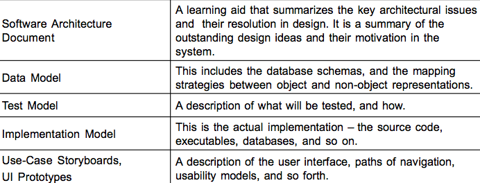
- System Sequence Diagram captures the system behavior, for a particular scenario of a Use Case, by illustrating the events that external actors generate to SuD, their order, and inter-system events
- It allows us to treat the system as a BLack Box
- System Sequence Diagram emphasizes those events that Cross the system boundary from actors to systems
- System Sequence Diagram should be done for the main success scenario of the Use Case, and frequent or complex alternative scenarios
- System Events & System Operations
- System event is an external event generated by an external actor to a system —> Stimulus
- System operation is an operation of the system that executes in response to a system event —> Response
- The set of all required system operations is determined by identifying the system evnets. The system events are derived from Use Case
( System 외부에서 Event 가 주어졌을때 해당 Event 에 대한 System 이 취한 동작 )
- The set of all required system operations is determined by identifying the system evnets. The system events are derived from Use Case
- System Sequence Diagram shows system events for a scenario of a Use Case, therefore it is generated from inspection of a Use Case
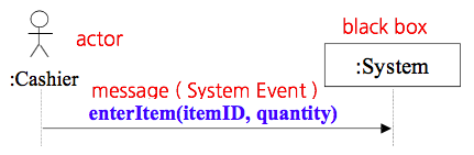
- Naming System Events / Operations
- System events and theri associated events should be Expressed at the (highest) level of Intent rather than in terms of physical input medium or interface widget
- Usually start with a “Verb” like add, enter, make …
- Showing Use Case Text
- The text provides the details and context
the diagram visually summarizes the interaction
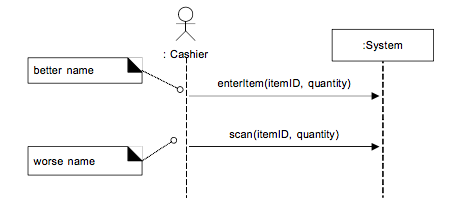
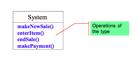
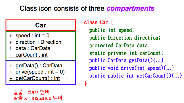
- Recording System Operations & Class Icon
- UML class icon provides a compartment to record operations for a type
- How To Make System Sequence Diagram
- Draw a line representing the system as a black box
- Identify each actor that directly operates on the system
Draw a line for each such actor - From the Use Case main success scenario text,
Identify the system ( External ) events that each actor generates. illustrate them on the diagram - Optionally, include the Use Case text to the left of the diagram